Fout in e-mailformaat
emailCannotEmpty
emailDoesExist
pwdLetterLimtTip
inconsistentPwd
pwdLetterLimtTip
inconsistentPwd

Nieuws
Start PCB Cutting? Wait a Minute, Let's Take a Look at these 11 Precautions First(1)
Generally speaking, it is necessary to avoid connecting the single wire using solid copper wire to the pad or try to avoid directly welding the wire to the PCB.
Even though it is technically possible to weld wires directly to pads, I do not recommend doing so. The bonding pad is originally small, so welding cannot firmly bond the wire to the surface of the copper plate, which often leads to the wire being too easy to pull out. It is better to use stranded copper wire for such welding, but I still recommend using wire to plate joint or plate-to-plate joint for welding, which is easier to operate.

If possible, try to use larger pads and wider wiring.
Using small pads connected to narrow wires is prone to problems. The circuit board I use has a 1-ounce thick copper layer, and I use small pads and connect narrow wires, so when I scratch the copper layer or the soldering iron contacts for too long, the copper layer will break. If the copper layer is overheated or scratched during welding, the narrow wiring will break, resulting in an open circuit. If the size of the welding joint is limited, small pads and narrow wiring may indeed be difficult to weld.
Understand the design of each part and analyze the solderability of the pad in advance.
Some parts are difficult to weld because of their design. The male pin is easier to weld from top to bottom rather than from bottom to top; If welded from the bottom, it may cause dislocation. The pins of some parts are wrapped with some kind of plastic shell. If these parts are through-hole parts, it is easier to weld from the bottom. If you need to connect materials welded from the top, you may need to add through holes for wiring. If the article is surface mounted and cannot be welded on the pad with a standard soldering iron, a solder paste and reflow pad must be used. If you need to weld multiple faces, you may need multiple ground plane datums.
Try to use single-sided circuit boards by redirecting parts in the layout.
If all items are concentrated on one side, it will be easier to operate, and in the long run, the cost of circuit boards will be lower.
Use a suitable drill bit to shorten milling time.
On several occasions, I used the wrong tool, resulting in a longer milling time. On one occasion, I even used a bit of the wrong size on the cutting layer suitable for a larger bit, resulting in damage to the bit. Larger through holes use exactly 1/32 drill bit, while smaller through holes require 1/64 drill bit. It is suitable to use a 1/16 drill bit in the boundary layer (also known as the outer boundary), which will not waste too much material, but also shorten the milling time. For example, Bantam milling software will tell you whether a drill bit is suitable for the cutting layer you choose. If applicable, the red mark will not appear. Before clicking start milling, please pay attention to the estimated time shown above. Try to operate one cutting layer at a time (through the hole, boundary, and wiring).
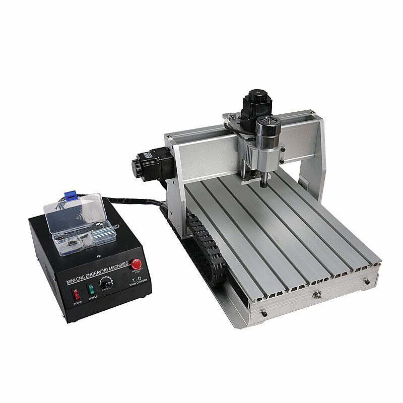
Make a purchase of cnc router pcb milling, best cnc for pcb milling, pcb cnc laser from China, you can get them at a good price if you have a large quantity. We hope to be your long-term partner.

